There are splitters for XLR but unless you spend big bugs on electronic isolation you are asking for trouble. Making your own cables will likely yield sub-optimal results. If any of your mics require phantom power this is especially likely to cause problems as the phantom power ends up returning down both legs of the split and sending phantom into the inputs of a computer sound card might be problematical–YMMV.
Many mixing desks have “Direct Out” connectors.
If a recorder is connected to the direct out connectors, the the signal path is:
Microphone → Mic Pre-amp in Mixer.
Mic Pre-amp in mixer → Mixer channels controls
AND
Mic Pre-amp in mixer → Direct Out → Line input of recorder.
Electronics in the mixing desk should ensure that the Direct Out is suitably isolated from the mixer channel.
First, your quote is attributed to me when in was made by J, R, D, Ltd–not that I care, just to keep the record straight !
I do disagree that “many” mixers have direct out; IMHO, only the higher-end pro desks have per-channel direct out. I can think of no consumer-grade mixer with such. I am willing to be persuaded by some examples!
Apologies for that. The forum software often messes up attribution with nested quotes and I didn’t notice that it had done so.
I agree that you’re unlikely to get such features on the very small mixers, but for mid-range home studio mixers:
Behringer: Most of the (older) Behringer desks have direct out on the microphone channels (I’ve not checked their most recent mixers), though in some cases these are “channel out” rather than “direct out” (they still call them “direct out” but on some models these outputs are pre-mix, post fader).
Phonic: Some of the Phonic mixers have direct outputs (example UM Helix 24 - I’ve not looked at the smaller Helix mixers).
Mackie 802 VLZ3 : Combined Insert/Direct Out on channels 1 and 2
If only 1 or 2 channel recording is required, many consumer grade desks have a couple of AUX outputs that could be used for pre-mix recording, and some have switch-able “ALT” outputs that could provide 1 or 2 additional recording channels.
Good info, I am familiar with Behringer and Mackie. I use the AUX outs myself as you suggest but this limits most consumer (and even mid-range pro) grade to a max of 4. Obviously, without compiling in ASIO support, Audacity can only handle 2 channels of input so this would work.
Now, the tricky part is that the OP is looking to record 16 channels with Audacity and ASIO. I personally think that whatever sound pod the OP eventually uses will come with recording software which will be more suitable than Audacity for this task. I would save each track individually in the supplied software then import them into Audacity for post-production. I did this with an 8 channel studio CD I recently produced but mixed down to stereo in the supplied software before importing into Audacity.
Very nice pro-grade mixer–no per-channel direct out. As it has 6 AUX outs and 2 (usable for your case) groups you could use these as 8 pass-thrus but would lose them for other uses. You can build your own isolated Ys but I would bite the bullet and buy, if it were up to me and I had the spare $$s !
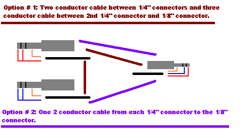
As long as your recording inputs have “Line” inputs with a reasonably high impedance (~ 20 k or more), then you could connect the “Channel Inserts” to a half-normalized patchbay. To do this you would need an “Insert cable” (“Y” cable) for each channel.
Example Insert Cable: http://www.thomann.de/fr/cordial_cfy_3_vpp.htm
Half-Normalized patchbays are available fairly inexpensively from Behringer or Neutrik.
This method is not suitable if the recorder has only low impedance microphone inputs (~ 600 Ohm)
The 6 AUX outs are actually four + two because the two (5 and 6) are switched between being AUX out and Effect on a per channel basis. Why would only 2 of the 4 groups be usable for my case?
Do you have a schematic for an Isolated Y? I did a quick Google search but couldn’t find one. Would that be the same as what the Manual calls an insertion cable?
I actually drew a schematic for an idea I had using the Insert I/O Jacks:
I figured that if I just used a mono plug it would cut off the signal from the mixer so there would be no output on that channel and that would kinda defeat the purpose of the sound system.
Then I figured I could use a stereo plug and short the Tip and Ring terminals together in each Insert I/O Jack and then put two mixer channels on one stereo channel as is illustrated in the schematic above. I actually built a board out of stuff I had that allowed me to essentially have this setup for testing two channels and it worked.
Now that schematic was originally made when I was planning on making an el-cheapo but I found that I didn’t have as many identical sound cards as I thought I did. I also saw a post on here someone made about making a USB sound device for much less than the commercial devices, don’t remember where it was now, unfortunately he didn’t post specifics. I am willing and able to assemble electronics if I can save money by doing so but I also believe in buying the right tool for the job as long as it is not too expensive.
Well that is enough for one night, it is getting late here.
in re. 4 + 2 that is why I said you would lose them for other uses–they are either AUX or Effects–so not more reverb on the vocals! As for the Groups, as per the manual the assign buttons are ganged 1/2 & 3/4 and (as opposed to the norm) are not split by the pan–so pressing 1/2 assigns to both 1 & 2 (I may have mis-read the manual).
My boss built his own “transformer isolated splitters” (that is what you need to Google) many years ago and we still use them for on-stage monitor mixing. He also just bought a second set but time is money and he’s getting well up into his 70’s now and probably has less fund soldering than mixing!
As for your schematic, in the 60’s I built huge computers for universities using nand gates, clock chips, diode arrays etc.; we silk screened our own boards and had a soldering wave tank; but…I think I was in the 60’s as I do not recall them! I have a lot of hard won experience as a sound tech but my ET days are more than 50 years ago. I will have to pass!
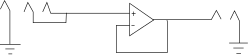
An easy (and much cheaper) method is to use an Op-amp buffer circuit (Op-amp follower).
Using an Op-amp follower circuit with an input from the insert connector on the mixer would be something like this:
Maybe you didn’t scroll down to the bottom of page 12 where it says:
9	PAN Control (Monaural Channels)
	 BAL Control (Stereo Channels)
The PAN control adjusts the signal’s pan positioning into the
Group 1-2 bus pair, into the Group 3-4 bus pair, and into the
Stereo bus’s L and R lines.
The BAL control knob sets the balance between left and right
channels. Signals into the L input (odd channel) feed to the
Group 1 and Group 3 buses and to the L line of the Stereo bus.
Signals into the R input (even channel) feed to the Group 2 and
Group 4 buses and to the R line of the Stereo bus.
I haven’t had need to use the groups much yet.
Cool sounds like a great guy.
That’s understandable
So what is the point of the OP-amp buffer here? It makes sure the input on the recording device does not get over driven?
The input impedance of the Op-amp buffer is very high, so effectively what the mixer sees is the Insert Send directly connected to the Insert Return, which is virtually the same as not having anything plugged into the Insert socket.
The output of the Op-amp “follows” the signal on its non-inverting input, but is isolated from it. This can then be fed into any input load, up to the drive capability of the Op-amp.
For a practical circuit you would probably want DC blocking capacitors on the input and output of the Op-amp, which would then allow a simple single rail supply to be used to power the Op-amp and a 2 resistor divider to determine “0 V” (for simplicity it could be battery powered).