<>
Look up “full wave rectifier”.
The bottom one is damaged from the point of view of sound. It has battery or DC voltage in addition to the “sound.” That’s what’s giving it the downward shift. You can’t hear battery voltage, but when it’s there, it can screw up tools and filters. Usually, this means you have a damaged computer, microphone, or sound mixer.
If you’re doing waveform or electronics tests, then all sorts of oddball things can happen.
There’s a philosophical discussion as to whether or not Audacity should manage waves you can’t hear. Many stand-alone sound mixers and sound managers won’t do that because in a vast majority of the time, it can get you into trouble.
Koz
I’m nit picking here but isn’t “sawtooth” a more accurate description than “triangle” ?
If you fully rectify a sawtooth wave you get a triangle wave, (not another sawtooth).
<<<but isn’t “sawtooth” a more accurate description than “triangle” ?>>>
Yes.
<<>>
Yes, but that’s not what the example is. The first trace of the bottom waveform is not a rectified version of the top. It’s going the wrong way. I think it’s just a second test with double the frequency and DC or “Pulsating DC” added. A negative “DC” voltage derived from the overall average of the RMS (or maybe average) value of the waves.
That would give you a single, negative-going sawtooth, wouldn’t it?
Koz
I agree. I was responding to Steve’s post …
full wave would put flat tops on the wave not go up and down with a negative voltage off set that is decaying like an exp(-x) modulating it
i would call the first wave a triangle with linear decay
the second is a sawtooth with a neg dc offset and decay following somethign like an exp(-x) plus (senior moment) some function that pins the max to the zero line
Are we doing someone’s homework? ![]()
What happens if you invert a full-wave rectified “triangle” wave?
(Clue: it’s not the same as an inverted full-wave rectified “sawtooth” wave)
Yes rectifying a triangular wave would produce another triangular wave with double the frequency,
But the waveforms shown are sawtooth not triangular, rectifying a sawtooth doesn’t change the frequency.
[BTW the sawtooth waves shown have the same type of slope so there hasn’t been an inversion]
<>
Sawtooth: Sawtooth wave - Wikipedia
It’s so much easier to give a relevant response when the question has context.
I think “half wave” is a pretty good description.
or perhaps a “negative going sawtooth”.
Just as a matter of interest, you can generate a pretty good approximation to that “half wave” with the following Nyquist code:
;type generate

(setq !TEMPO 180) ; beats per min
(setq piano-key A1) ; note in standard MIDI notation

(setq i (/ 60.0 !TEMPO)) ; note length

(defun env (s-in) ; apply envelope
  (setq t (get-duration (* i  0.7)))
  (mult s-in (pwl 0 1 t 0.5 t 0 1)))

(defun note (pitch dur) ; create waveform
  (env (sum -0.25 (mult 0.25 (osc pitch dur *saw-table*)))))

(note piano-key i) ; generate the note
I refer the honourable gentleman to the answer I gave a few post ago …

That is part sawtooth (or possibly square wave) and part exponential, (like charging a capacitor).
<<>>
Except for the downward going bits.
Koz
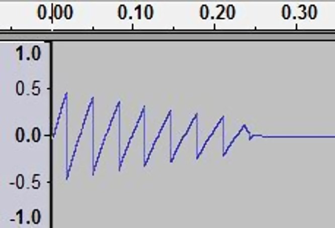
The first is a sawtooth with decreasing amplitude and no DC component.
The second is also a sawtooth with decreasing amplitude, but it has a negative DC component proportional to the amplitude.
Not useful in audio, but analogous nonetheless, is what’s called a “DC restorer” circuit which is used in TV sets that have AC coupled video amplifiers. The same circuit, given the first waveform (at the frequency of the 2nd one) would produce the second waveform.
The DC restorer is just a diode across the load side of a coupling capacitor, which clamps the positive extreme of the waveform to a fixed voltage (in TV, it’s the top of the horizontal sync pulse). In the valve days, the control grid of the sync separator typically served as the diode. The top of the sync pulse serves as a reference level just beyond black. Without DC restoration, the black level would vary from beyond black to gray as the contrast of the scene varied. In color TV, the saturation levels would be totally hosed.
The waveform exponential.gif looks like a sawtooth which has been AC coupled with a time constant which is too short. The short time constant high-pass filters the waveform. Near the top of the original sawtooth, the output of this (single pole) high-pass filter approaches a DC value proportional to the slope of the rising portion of the waveform. The flat bottom suggests that the resulting waveform has been clipped by a later stage, and the fact that the clipping level of the bottom varies with amplitude suggests that the result is AC coupled again in a later stage.