brick wall low pass filtering

It is sometimes necessary to use very steep low pass filters, for example for preventing aliasing when resampling or pitch shifting.

Nyquist provides a fairly steep 8th order low pass filter (48 dB/Oct) with:

(lowpass8 sound frequency)

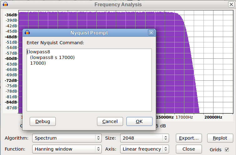
If this is not steep enough for a particular application, the filter may be “nested” so that it is applied multiple times, for example:

(lowpass8
  (lowpass8 sound frequency)
  frequency)

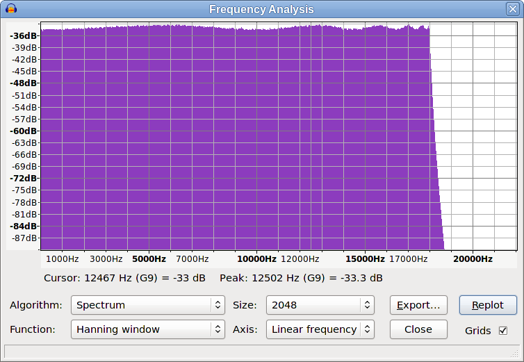
Nesting up to about 10 lowpass8 filters can be used to good effect by looping through the filter:

;;; steep low pass filter
(defun lp-steep (sound hz)
  (setq hz (* 0.94 hz))
  (dotimes (count 10)
    (setf sound (lowpass8 sound hz)))
  sound)

; apply a steep 1000 Hz filter to the selection
(lp-steep s 1000)

This provides a pretty steep cut-off, though there is a fair amount of attenuation before the set filter frequency.
The lp-steep function lowers the cut-off frequency to 94% of its input value so as to provide a high degree of attenuation at the set frequency.


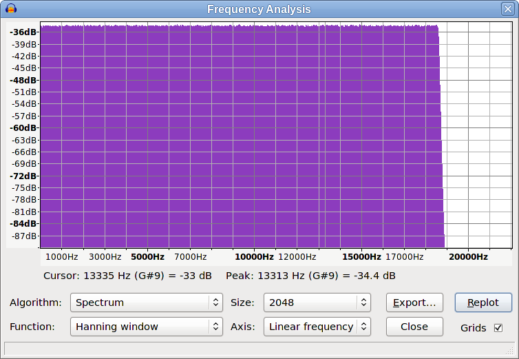
For an even sharper cut off, here is a 100th order Butterworth filter.
The characteristics are that it has an extremely steep cut-off with very high attenuation at the filter frequency (around -90 dB at 1 kHz).
Many thanks to kai.fisher for doing most of the leg work on this https://forum.audacityteam.org/t/chebyshev-type-i-and-butterworth-hp-lp-filters/24241/1 and to S. Smith, author of “The Scientist and Engineer’s Guide to Digital Signal Processing” for publishing the biquad equations on which it is based.

(defun lp100 (sig frequency)
  (defun butterworth (s1 fc n)
    (defun Coeffs (ffc p n)
      (let* (;Calculate pole location on unit circle in z-plane
             (ReP (- (cos (+ (/ pi (* n 2.0)) (* (- p 1.0) (/ pi n))))))
             (ImP    (sin (+ (/ pi (* n 2.0)) (* (- p 1.0) (/ pi n)))))  
             ;s-domain to z-domain conversion
             (t (* 2.0 (tan 0.5)))
             (t2 (* t t))
             (wfc (* 2.0 pi ffc))
             (m2 (+ (* ReP ReP) (* ImP ImP)))
             (d (+ 4.0 (- (* 4.0 ReP t)) (* m2 t2)))  
             ;Lowpass prototype coefficients
             (x0 (/ t2 d))
             (x1 (/ (* 2.0 t2) d))
             (x2 (/ t2 d))
             (y1 (/ (- 8.0 (* 2.0 m2 t2)) d))
             (y2 (/ (- -4.0 (* 4.0 ReP t) (* m2 t2)) d))  
             ;Transform Lp prototype filter coefficients to actual LP or to HP
             (k (/    (sin (- 0.5 (/ wfc 2.0)))  (sin (+ (/ wfc 2.0) 0.5))))
             (k2 (* k k))
             (d (+ 1.0 (* y1 k) (- (* y2 k2))))  
             ;derive coefficients
             (a0 1.0)
             (a1 (/ (+ (* 2.0 k) y1 (* y1 k2) (- (* 2.0 y2 k))) d))
             (a2 (/ (+ (- k2) (- (* y1 k)) y2) d))
             (b0 (/ (+ x0 (- (* x1 k)) (* x2 k2)) d))
             (b1 (/ (+ (- (* 2.0 x0 k)) x1 (* x1 k2) (- (* 2.0 x2 k))) d))
             (b2 (/ (+ (* x0 k2) (- (* x1 k)) x2) d))  
             ;Determine gain of filter
             (ga (+ a0 (- a1) (- a2)))
             (gb (+ b0    b1     b2 ))
             (g (/ ga gb))
             ;Apply gain so that passband is unity.
             (b0 (* b0 g))
             (b1 (* b1 g))
             (b2 (* b2 g)))
      ;Output coefficients
      (vector a0 a1 a2 b0 b1 b2)))
    ;convert cut-off frequency to a fraction of sampling rate
    (let ((ffc (/ (* 0.94 fc) *sound-srate*)))
      ;loop once for each biquad
      (dotimes (p (/ n 2))
        (setf coef (Coeffs ffc (1+ p) n))
        (setf a0 (aref coef 0))
        (setf a1 (aref coef 1))
        (setf a2 (aref coef 2))
        (setf b0 (aref coef 3))
        (setf b1 (aref coef 4))
        (setf b2 (aref coef 5))
        (setf s1 (biquad s1 b0 b1 b2 a0 a1 a2)))
      s1))
  ; 100th order butterworth
  (butterworth sig frequency 100))


; apply a 'brick wall' 1000 Hz filter to the selection
(lp100 s 1000)

As you go through that, I can’t help thinking about all the grief we go through to make stereo FM work.

The audio show has to go up to 19 KHz (stereo pilot tone) and drop dead. Nothing past that and it usually means you have to start drooping at 17KHz in order to get a good dip at 19. But you can’t just wack off everything at and past 19 because that does serious damage to the sound and causes overmodulation. The Nyquist thing says complex waves are created by multiple sinewaves interacting with each other. If you lose some of sinewaves through truncation, some of the others are allowed to run wild and some are bigger than the original sound.

You can totally fix that, but then the distortion goes up but that’s OK, because you can reduce the volume of the show to help there. That prompts a call from the program director wondering why the modulation monitor isn’t hanging just a gnat’s eyelash shy of the overload light. See: Loudlness Wars.

But that causes…etc. I’m clear that some of that is an artifact of analog circuitry, but a lot it isn’t. Nyquist didn’t go to Côte d’Azur on vacation just because systems went digital.

Koz

That’s similar to using the second bit of code:

(lowpass8 
  (lowpass8 s 17000)
  17000)

This effectively gives you a 16th order low pass filter, which I’d guess is around the practical limit for an analogue filter.
The highest order analogue filter that I’ve actually seen was a 12th order Butterworth filter (lots and lots of expensive high precision capacitors). I guess that FM radio equipment may go a little higher, but it does not surprise me that your rolling off at 17 kHz.

It is possible to achieve a steeper cut-off by using a Chebyshev filter, but the down side is that Chebyshev filters have ripple close to the cut off frequency, and that’s where you can get frequencies close to the cut off “running wild” as you say. In the worst case, the filter can go into oscillation, and that’s when things start smoking.

This is a plot of white noise, filtered with the above code, and as you predicted there is a marked roll off from around 17 kHz


This is the result with a 12th order Chebyshev filter. You’ll notice that the filter cut off is much steeper, but the response in the pass band is not flat - some frequencies are measurably higher than others:

The beauty of Butterworth filters is that they are critically damped to provide the steepest possible slope with no ripple. Of course it is not possible to get the damping exact with analogue components due to manufacturing tolerances, so analogue filters are made with a slightly less steep cut off so as to avoid ripple in the pass band. The higher the order of the filter, the more components are required and the tighter the tolerances must be, thus imposing a practical limit.
Fortunately these limitation do not exist for digital filters. The “components” can be accurate to something like 12 decimal places and by implementing a loop the “component count” can run into thousands. This the final (long) piece of code represents a 100th order Butterworth filter with “components” manufactured to around +/- 0.00000000001 %