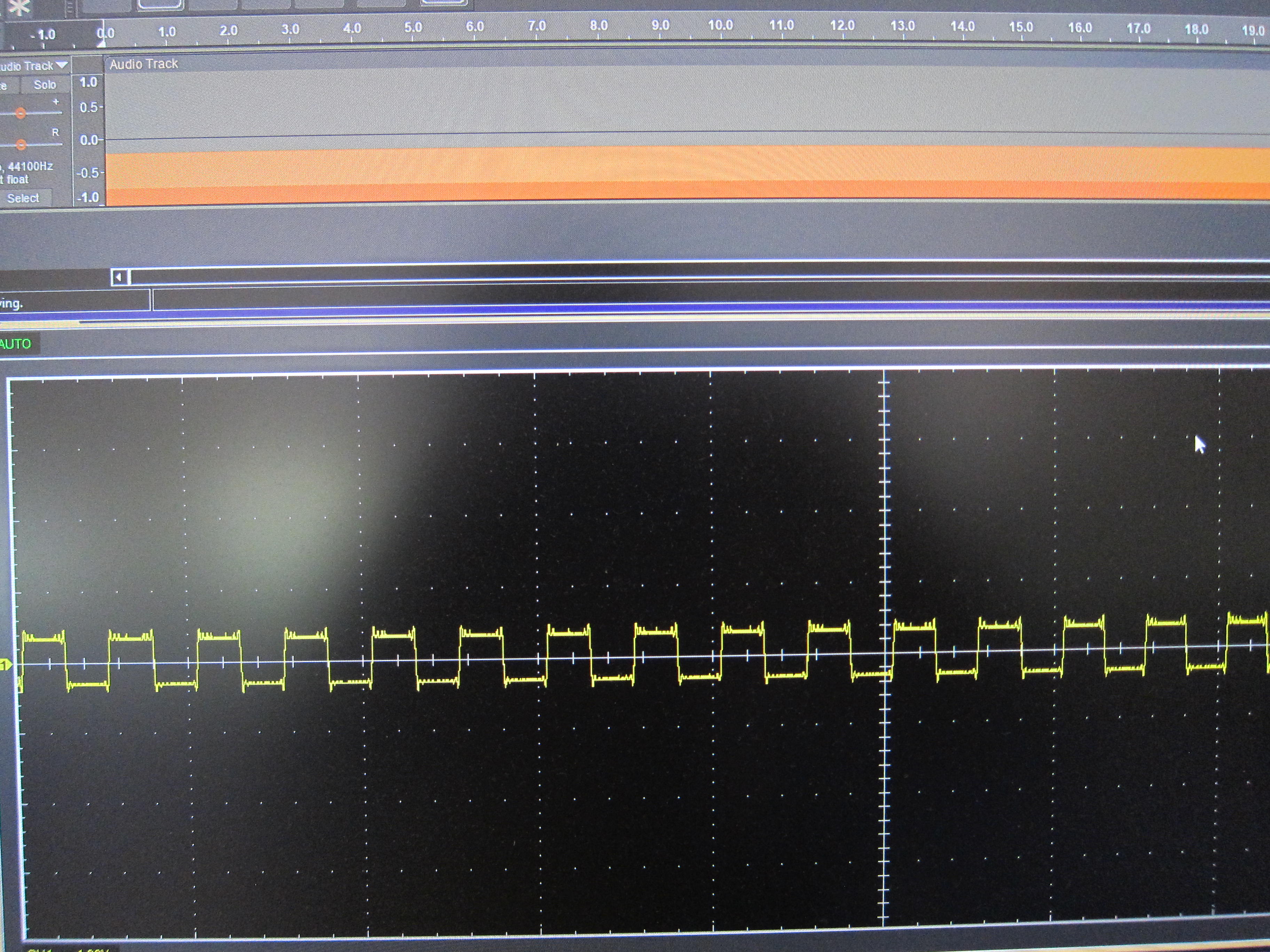
The adjusted DC offset shows correctly on screen but the output from my PC remains unchanged. I have tried with both the headphone out and a USB DAC. See photo below of sample track and resulting trace of an oscilloscope connected directly to PC out.
Can someone please advise why this is happening and how to fix? I recall being able to do this successfully in either CoolEdit or Audition.
I am expecting the real world output of the sound card or DAC to be offset the same as is indicated in Audacity. In the case illustrated, offset about 1V downward, being half the 2Vpp swing. BTW the same problem exists when I try to offset the signal upward. I see no point DC offsetting the signal in Audacity if it cannot be output as an actual signal. How can I make this work?
Now I remember how I made it work. I used a cheap USB sound card (see below) and shorted the output capacitor. This effectively turns it into a class A amp. Accordingly, the chip gets hot and needs extra heatsinking, but over time the device did not fail.
There are many uses for a DC offset signal that have nothing to do with audio listening. A similar approach can be used to create a front end for a sound card oscilloscope.
Not necessarily.
Just because there is a DC bias, does not make in class A.
It could be class AB or even quasi AB, amongst others.
Assuming of course the bias sits at the optimal point to begin with.
Getting it wrong, will cause the amp to either bottom out, clip or even “motor-boat” due to the
extra gain which if not controlled, can cause oscillations.
Just applying an arbitrary voltage is like taking pot shots in the dark.
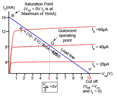
To properly bias an amplifier, certain parameters like the input transistor’s hfe (or beta), base current and collector
current limits are needed.
These will be pretty difficult to obtain from some undocumented amp circuit from some far eastern USB device.
All of the above, applies to the input stages.
You seem to be affecting the output stage without compensating the input stage/s, never a good idea.
Many modern output amp stages, create their own VCC/2 DC point and then the output transistors,
will swing negative and positive around that point.
By shorting out the capacitor, all you have done is shifted that point.
There is no advantage to it.
All it does is either overheat the final stage, cause distortion or worse, destroy the amp.
(Not to mention that any load like a speaker connected to it, will now also have DC on the coil, not good).
So in short (no pun intended), messing with an output stage, does not turn the amplifier into class A.
It will however, turn the amp into a heater.
What I meant was that shorting the output cap causes mid point of the voltage swing to sit at about half rail and draw continuous current like a class A. The swing is therefore unipolar. That is really all I want. I can deal with the heat. It just happens to work as described for my application … which does not involve driving speakers.
Using an oscilloscope to monitor the result, I have not experienced the problems you mention. The device is a cheap sound card. I have used it this way for hours on end. Something I would not do with a hi-fi amp. If it ever burns up, I will buy another for $20. Of course your comments are valid in the strict context they were made.
Just for information, the correct technical term is “DC coupled”.
Most audio amps are DC decoupled (usually via decoupling capacitors).
Whether or not it is safe to short out the decoupling capacitors depends on the design of the amp. In some cases it could cause the output to float at a high voltage level, which could potentially damage any other equipment that is connected to it.
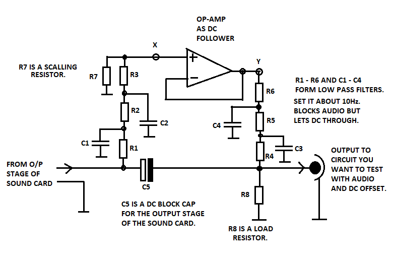
If you want/need to test a circuit with audio and DC from a sound card, a better (and safer) way is to use an opamp
as shown below.
The opamp acts as a DC follower which has a lowpass filter before and after it.
The DC in the final stage of the sound card is not messed with as it’s DC blocking cap is still in series, shown as C5 in the schematic below.
Note that the resistors in the output lowpass filter, also act as current limiters for the opamp.
This way, no excess heat and it’s even safe to drive it into a short circuit.
R7 acts as a voltage divider (along with R1 - R3) which allows you to scale the DC offset.
If you need higher order lowpass filters, add another cap (to ground) at points X and Y.
I haven’t included any component values, as they will depend on your exact requirements.
The opamp can be powered from USB provided you filter it well and you don’t need more than 5V at around 100mA.
Note that if you require 2 channels (stereo) then two identical circuits will be required.
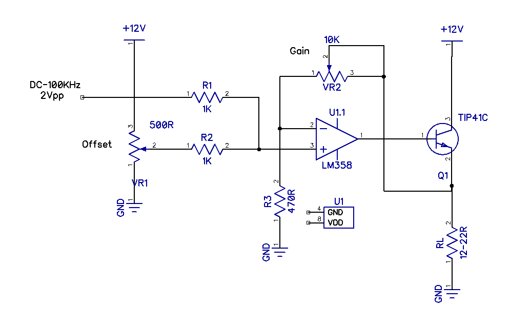
The simple circuit below includes variable DC offset. No inline caps required. Never had a problem using it with any sound card. It is set up to provide unipolar drive to a magnetic coil (RL) for experimental purposes.